MANUAL
TRANSMISSION TOYOTA
(please click the title for referrence web )
(C50-C56)
Introduction Manual Transmission
The manual transmission transfers power from the engine to the propeller shaft. It converts and multiplies rotational speed, allowing engine RPM to remain in it's limited optimal power range while providing a wide range of RPM to the propeller shaft; which, in turn, controls vehicle speed. Multiple gear sets within the transmission provide gear ratios to best utilize the engine's torque.
A gear ratio of about 4:1 in first gear provides high torque to begin moving the vehicle. In contrast, a higher gear ratio of about 1:1 reduces engine speed at higher vehicle speeds when less torque is required to maintain momentum. Understanding manual transmission design features increases your knowledge of transmission operation, and provides for easier and more accurate problem diagnosis.
Input Shaft
|
The input shaft also known as a main drive gear or clutch shaft is
driven by the clutch disc and drives the counter gear shaft. The
input
shaft is supported by the pilot bearing at the end of the
crankshaft and
a bearing at the front of the transmission case.
|
Counter Gear
Shaft
|
The counter gear shaft also known as a cluster gear drives the
gears (1st, 2nd, 3rd, and 5th) on the output shaft. This shaft is
supported by bearings in the intermediate plate, at the front of
the
transmission case, and in the extension housing.
|
Output Shaft
|
The output shaft also known as the main shaft drives the propeller
shaft. It is splined at the rear to allow a sliding connection to the
propeller shaft. The output shaft gears rotate on the shaft and are locked to
the shaft by synchronizers. The synchronizers are splined to the output
shaft. The output shaft is supported by a pocket bearing at the rear of the
input shaft, a bearing at the intermediate plate and a bearing at the
extension housing of the transmission.
|
Components
1 RH Bearing Retainer Sub-assembly
2 RH Bearing Retainer O-ring
3 RH Bearing Retainer Oil Seal No. 1
4 O-ring
5 Side Gear Shaft Holder Bearing
6 Snap Ring
7 RH Bearing Retainer Oil Seal No. 2
8 Ring Gear Mounting Case Washer No. 2
9 Center Differential Case Tapered Roller
Bearing RH
(Outer Race)
|
10 No. 2 Plug
11 Gasket No. 2
12 Gasket No. 1
13 No. 1 Plug
14 Drain Plug
15 Drain Gasket
16 Lock Nut
17 Specified Torque
18 Non-reusable Part
|
Gears
|
Gears transfer engine power from the input shaft, through the
counter
gear shaft, to the output shaft. There are five forward gears and
one
reverse gear. Only one gear is engaged at a time.
|
Forward Gears
|
All forward motion gears are helical gears because of their smooth
and
quiet operating characteristics. Helical gears create end thrust
under
load, and therefore have a thrust surface on the side of the gear.
Gear
side clearance is limited to reduce noise and potential damage,
which
could result from gear motion.
|
Reverse Gears
|
Reverse requires an additional gear in the gear train. A reverse
idler gear is used to change the direction of the output shaft for reverse. The
reverse gear is a straight cut spur gear and does not have a synchronizer.
Spur gears are suitable for this application because they shift into mesh
more easily than helical gears, and they don't generate end thrust under
load.
Straight cut gears may create a whine or light growl during
operation.
|

Bearings
|
Bearings and bushings are used to support shafts in the
transmission.
Depending upon design, transmissions use a wide variety of
bearings,
including:
Ø
Needle bearings _ can support large side loads
but are unable to control end thrust loads. Individual needles are housed in
a single enclosure or a split bearing holder. They are used in most forward speed
gears.
Ø
Ball bearings _ can support moderate to high
side and thrust loads and are commonly used for the input shaft and output
shaft.
Ø
Roller bearings _ can support large side loads
but are unable to control end thrust loads. Individual rollers are housed in
a single enclosure.
Ø
Plain bushings _ can support large side loads
and allow free in and out movement. Bushings are used on the reverse gear and
to support the propeller shaft slip yoke in the extension housing.
|

Synchronizer Assemblies
Synchronizer
assemblies are used to make all forward shifts and to assist reverse gear engagement.
The role of the synchronizer is to allow smooth gear engagement. It acts as a
clutch, bringing the gears and shaft to the same speed before engagement
occurs.
Synchronizer
components help make the speeds equal while synchronizing the shift. Gears on
the output shaft are in mesh (contact) with gears on the counter gear shaft at
all times. Consequently, when the counter shaft turns, the gears on the output
shaft rotate. When shifting gears, the synchronizer ring supplies the friction
force, which causes the speed of the gear that is being engaged to match the
speed of the hub sleeve. This allows the gear shift to occur without the gear
and hub sleeve splines clashing or grinding.

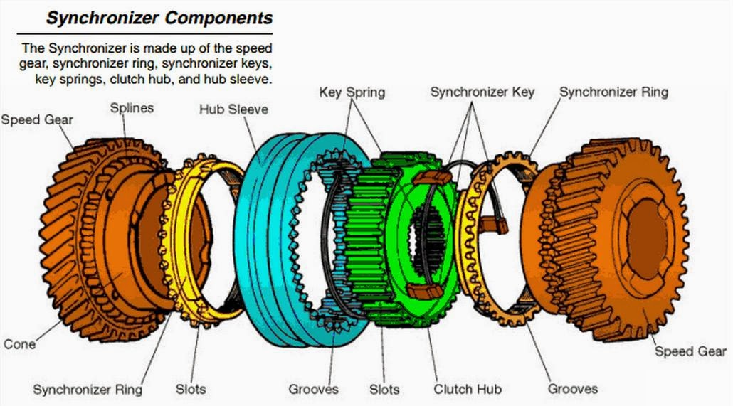
Synchronizer Components
The
synchronizer mechanism is constructed of the following components:
- Ø The speed gear is mounted on the output shaft. A needle roller bearing is installed between the speed gear and the output shaft, allowing the gear to rotate freely on the shaft.
- Ø The synchronizer ring _ also called a blocker ring _ is made of brass and is installed on the conical portion of the gear. Narrow grooves are cut in the inside area of the synchronizer ring to provide the necessary clutch action of the gear. Three equally spaced slots are cut on the outside surface for the synchronizer keys to fit into.
- Ø Two key springs are installed, one on each side of the clutch hub to hold the synchronizer keys in place against the hub sleeve. The clutch hub is fit to the output shaft on splines and is secured by a snap ring.
- Ø Three synchronizer keys are installed in the three equally spaced slots in the clutch hub and are aligned with the slots in the synchronizer ring.
- Ø The hub sleeve has internal splines that slip over the clutch hub splines, engaging the spline teeth of the speed gear. An internal groove cut in the center of the hub sleeve splines centers the hub sleeve. The hub sleeve is indexed by the three spring loaded synchronizer keys.
1st Stage Initial Synchronization
As the
shift lever moves, the shift fork moves the hub sleeve to the right causing
the spring loaded keys to push the synchronizer ring against the cone clutch
surface of the gear.
Engagement
of the synchronizer ring to the cone
clutch on the faster spinning gear cause the synchronizer ring to rotate,
about one half the width of a spline.
|
 |
2nd Stage Synchronization
When the
shift lever is moved further, the force (which is applied to the hub sleeve) overcomes
the force of the synchronizer key springs. The hub sleeve moves over the
detents of the keys.
This
movement also causes more pressure to be exerted on the synchronizer ring and
gear.
The
grooves on the inside surface of the ring help to cut through the oil film on
the conical surface of the gear. This ensures that the ring will provide the
needed clutching action for engagement.
The
taper of the sleeve spline pushes against the taper of the ring teeth,
causing added pressure to the gear cone. As the gear slows to the same speed
as the hub and sleeve, it will rotate slightly backward to allow alignment of
the splines.
The synchronizer
ring and gear splines line up at this time and the splines of the hub sleeve
are ready to engage.
|
 |
3rd Stage Synchronized Meshing
When the
speeds of the hub sleeve and the gear become equal, the synchronizer ring is
not in contact with the key.
The ring
and gear are free to move and the splines of the hub sleeve can engage
smoothly. The sleeve continues to move over the splines of the speed gear,
locking the key to the gear, completing gear engagement.
|

|
Multi-Cone Synchronizer
Some transmissions use two or three cone synchronizer units.
Multiple cone synchronizers have more surface area available to provide low shift
effort for the lower gear ranges.
The two cone synchronizer is so named from
the two cone shaped surfaces which make up the assembly. The middle ring
provides two cone surfaces and almost twice the surface area to slow the gear
to the speed of the output shaft. In a two cone synchronizer, the inner and
outer rings are indexed together and turn with the transmission output shaft.
The middle ring is indexed to the gear and they turn together driven by the
input shaft.

The three cone synchronizer is so named from
the three cone shaped surfaces which make up the assembly. In addition to the
middle ring providing two cone surfaces, the speed gear has a third cone
surface providing three surface areas to slow the gear to the speed of the output
shaft.

Toyota Manual Transaxle
(C50-C56)
Front wheel drive vehicle utilizes a transaxle to transfer power from the engine to the drive wheels. The transmission portion of the transaxle shares many common features with the transmission. Differences in design include: number of shafts, powerflow, and the addition of final drive gears

Input Shaft
|
The input shaft connects to and is driven by the clutch disc. The drive
gears are located on the input shaft, one for each forward speed and
reverse. The input shaft is supported by bearings at the front and rear
of the transaxle case. No pilot bearing is needed.
|
Output Shaft
|
The output shaft includes a driven gear for each forward speed. The output shaft also includes the drive pinion, which drives the final drive ring gear on the differential. The output shaft is supported by bearings at the front and rear of the transaxle case.
|
Differential
|
The differential also also known as a final drive divides powerflow between the half shafts connected to the front drive wheels.
Power exits the output shaft through the drive pinion gear driving the final drive ring gear on the differential case. The ring gear and drive pinion gear are helical gears, and have a gear ratio similar to that in a rear axle. This gear set operates quietly and doesn't require critical adjustments as in the rear axle hypoid gear set.
|
Open Differential
|
The simplest type of differential is called an open differential. It is constructed of a final drive ring gear, side gears, pinion shaft and pinion gears. The ring gear is attached to the differential case. The pinion gears mount to the pinion shaft attached to the differential case. The side gears mesh with the pinion gears and transfer the rotation of the differential case to the side gears, which turn the drive axles.
When a vehicle is going straight, the pinion gears do not rotate, and both wheels spin at the same speed. During a turn, the inside wheel turns slower than the outside wheel and the pinion gears start to turn, allowing the wheels to move at different speeds.
|

Forward Gears
|
All forward motion gears are helical gears and are in constant mesh. In
each pair of gears, one gear is secured to the shaft and one gear floats
on the shaft next to the synchronizer assembly
|
Reverse Gears
|
Reverse requires an additional gear in the gear train. A reverse idler
gear is used to change the direction of the output shaft for reverse. The
reverse gear is a straight cut spur gear and does not have a
synchronizer
|


Bearings
|
Bearings are used to support the shafts, gears and the differential in the transaxle: gears use needle bearings; shafts use roller, ball, and tapered roller bearings.
|
Gear Bearings
|
Needle bearings are used in all gear applications to insure durability. Split needle bearings provide even load distribution. They also resist fretting better than the one piece bearing. Fretting is the surface damage that occurs on the bearing from vibration existing in the contact surfaces
|
Shaft Bearings
|
Transaxle shafts use roller bearings, ball bearings, and tapered roller bearings. each bearing type offers unique application characteristics.
|
Roller Bearings
|
Roller bearings can handle large side loads, but provide no thrust
support. They are located on the engine side of the input and output
shafts.
|
Ball Bearings
|
Ball bearings are used as support bearings opposite the roller
bearing on the input and output shafts because they can handle a
moderate to high thrust load as well as side load
|
Tapered Roller
Bearings
|
Tapered roller bearings handle large side and thrust loads and are
used in pairs with the cones and cups facing in opposite directions on the ends of the same shaft.
|
No comments :
Post a Comment